As processor power and rack density increase, thermal management has become a primary factor in data center design. As processor power levels rise and advanced packaging introduces more localized heat density, the limitations of traditional air-based cooling approaches are increasingly evident. Cooling remains a significant contributor to facility energy consumption, often accounting for 30 to 40% of total power use in conventional data centers, with most non-IT energy consumed by thermal management (U.S. DOE; U.S. Congressional Research Service).
As rack power densities increase, the effectiveness of air cooling reaches a clear physical limit. Conventional air-cooled designs are typically viable up to 10 to 15 kW per rack, with optimized airflow and containment extending into the 20 to 30 kW range. Beyond this point, the airflow required to maintain temperature control becomes impractical, and thermal consistency degrades. At densities exceeding roughly 30 to 40 kW per rack, air cooling alone is no longer sufficient to meet performance and efficiency requirements, making liquid cooling the more effective and scalable solution, as reflected in industry and the Uptime Institute Cooling Systems Survey 2025.

Direct-to-chip (DTC) liquid cooling has therefore become a necessity, particularly in AI and high-performance computing environments. The key to effectively deploying the technology is understanding each processor’s design and performance characteristics and selecting the right approach for its unique requirements.
In this paper, we’ll explain the four major technologies used in DTC liquid cooling – microchannel cold plate, microconvective cold plate, hybrid cold plate, and direct to die – and highlight where each is most effective in today’s compute environments.
Processor Architecture, Hot Spots, and the Cooling Stack
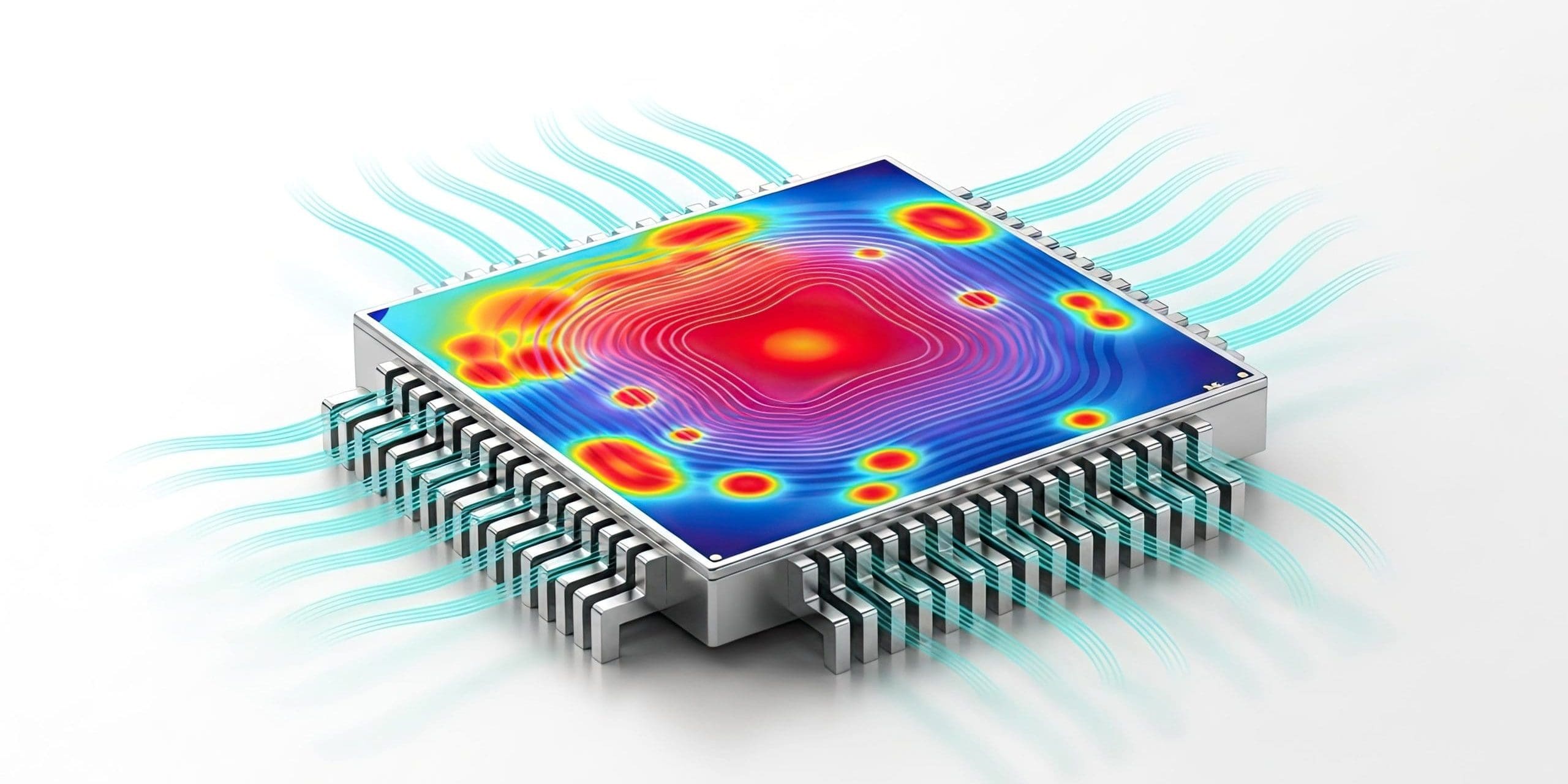
A processor (CPU or GPU) consists of a silicon die containing billions of transistors, where electrical activity is converted directly into heat. This heat is not uniformly distributed. Instead, each processor develops a distinct thermal profile driven by its physical layout and workload behavior, resulting in localized regions of very high heat flux. These hot spots shift dynamically as compute demand moves across cores, accelerators, and functional units.
Modern AI and high-performance processors further increase this complexity by integrating High Bandwidth Memory (HBM) within the same package. HBM consists of vertically stacked memory dies positioned adjacent to the compute die on a shared interposer, creating a tightly coupled compute and memory architecture. While this improves performance and bandwidth, it introduces competing thermal requirements within a highly constrained physical footprint.

The compute die generates the highest heat flux, with concentrated hot spots tied to active processing regions that can change rapidly with workload. In contrast, HBM stacks typically operate at lower heat flux but are significantly more sensitive to temperature. As memory utilization increases, particularly in AI training and inference workloads, HBM power and heat generation rise while allowable temperature margins remain tight. This creates a coupled thermal challenge, where overall system performance depends on simultaneously managing extreme, localized heat on the compute die and maintaining stable, lower temperatures across adjacent HBM regions.
Liquid cooling addresses these constraints by removing heat at the point of generation with significantly higher efficiency than air cooling. Liquid cooling can also target the hottest areas of the die, delivering superior heat flux management, temperature uniformity, and thermal control compared to air cooling.
The Cooling Stack
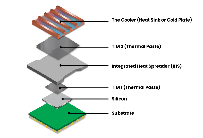
Because the raw silicon die is mechanically fragile, it is integrated into a carefully engineered, multi-layer package that provides structural support and enables effective heat transfer. The bulk silicon layer, or integrated heat spreader (IHS), primarily improves die integrity and manufacturing yield, while also serving as the interface between the silicon and the cooling solution.
- Substrate: The delicate silicon die is mounted on an organic printed circuit board (PCB) substrate, which provides physical protection and routes power and data pins to the motherboard.
- Integrated Heat Spreader (IHS): A metal lid (typically made of nickel-plated copper) is placed directly over the silicon die. It protects the die and spreads the concentrated heat across a larger surface area. Not all dies have an IHS, but they are becoming more common as die sizes increase.
- Thermal Interface Material (TIM): Thermal interface materials fill microscopic gaps between adjacent surfaces in the cooling stack to enable efficient heat transfer and minimize thermal resistance. In lidded designs, two TIM layers are typically present: TIM 1 between the silicon die and the IHS, and TIM 2 between the IHS and the cold plate. In lidless (direct-to-die) configurations, only a single interface layer is used, often referred to as TIM 1.5, positioned directly between the silicon and the cooling solution.
- The Cooler: The final layer is the cooling apparatus itself. For air cooling, a heat sink with metal fins pulls heat away from the IHS and exhausts it into the surrounding air. For liquid cooling, this is a cold plate or lid that absorbs heat into a circulating liquid which is then pumped to either a radiator, or a CDU outside the server for dissipation.
Direct to Chip Liquid Cooling Approaches
Direct-to-chip liquid cooling encompasses a range of approaches that differ in how they deliver coolant to the processor and remove heat from the package. These designs vary in where they interface within the cooling stack, how they manage heat transfer, and how they balance performance, complexity, and system constraints.
The following sections outline the primary architectures used in direct-to-chip cooling, along with their respective design characteristics, advantages, and tradeoffs. Understanding these differences is critical to selecting the right approach for a given processor, workload, and deployment environment.
Microchannel Cooling
Microchannel cold plates remove heat by routing coolant flow across the IHS through a network of channels. Heat is transferred from the chip to the cold plate channel walls by conduction and removed from the cold plate by the fluid flowing through the channels. In this approach, performance depends on the channel geometry, surface area, and the movement of coolant through the flow path.
This approach provides efficient heat removal across the full device surface at relatively moderate flow and pressure requirements. As a result, it is well suited for a wide range of systems, particularly those with constrained flow budgets or where predictable, uniform cooling is effective.
However, because heat transfer occurs as fluid moves along the channel, coolant temperature increases along the flow path, which can reduce downstream cooling effectiveness and limit the ability to address multiple highly localized hot spots. As silicon heat flux and power density rise, and processor architectures become more spatially complex, these characteristics can constrain microchannel designs’ ability to maintain uniform thermal performance, particularly in scenarios with concentrated, dynamic heat loads.
Microconvective Cooling

JetCool’s patented microconvective cooling takes a different approach. Instead of relying on bulk fluid flow across the silicon surface, these systems use arrays of engineered microjets and internal flow structures to deliver fresh coolant directly to targeted regions of the device.
Microjet impingement creates highly effective local heat transfer, while secondary flow structures in the cold plate promote mixing and removal of heated fluid. This enables effective cooling of concentrated hotspots and supports more uniform thermal performance across the non-uniform heat maps typical of today’s processors. This approach is particularly well suited for devices with high localized heat flux, such as HBM, where targeted cooling can improve thermal control and enable higher sustained performance.

While they offer strong capability for managing high heat flux and complex thermal profiles, Microconvective cold plates require sufficient flow and pressure to support jet formation and maintain effective coolant delivery, typically resulting in higher flow rates and pressure drop than microchannel approaches. As a result, performance is closely tied to system-level design and operating conditions, including flow distribution, manifold design, and fluid quality.
Hybrid Cooling
This approach allows the cold plate to apply jet cooling in regions of highest heat flux, while using microchannel flow across the remaining areas. By reserving microconvective cooling for true hotspots, such as HBM or dense compute regions, the design can target the areas where heat removal is most challenging, while avoiding the flow and pressure penalties associated with high-intensity cooling across the entire device area. The result is a balanced system that improves overall thermal performance while maximizing the use of flow, pressure, and pumping energy.
The tradeoffs center on design complexity and integration. Hybrid architectures require accurate mapping of heat flux across the device and careful coordination between regions to maintain balanced flow and consistent performance. Transitions between cooling zones must be well managed to avoid imbalance or local inefficiencies, resulting in a more optimized solution that demands greater engineering precision to execute effectively.
Direct-to-Die Cooling
This approach is particularly effective for extreme heat flux conditions, where traditional cold plate designs struggle to maintain performance without excessive flow or pressure.
The tradeoffs center on integration, reliability, and serviceability. Because the cooling structure is tightly coupled to the processor package, direct-to-die designs require precise sealing, materials compatibility, and strict control of fluid quality.
Direct interaction with silicon or near-silicon layers increases sensitivity to contamination and places greater emphasis on long-term material stability. In addition, these solutions can be more complex to deploy and service, as they are less modular than traditional cold plates. The result is very high performance at the device level, with increased installation and operational requirements to ensure consistent, reliable operation.
Comparing Technologies
Each direct-to-chip cooling approach addresses different thermal challenges based on heat flux, power density, and spatial heat distribution.
- Microchannel-based cooling provides efficient and reliable heat removal across the full device surface. By leveraging flow across engineered channel geometries, it delivers stable and predictable performance with moderate flow and pressure requirements, making it well suited for a wide range of applications and system conditions.
- Microconvective cooling is best suited for high heat flux conditions, HBM, and highly non-uniform heat maps, where localized hotspots can significantly exceed average device power. Delivering coolant directly to these regions enables strong thermal control in applications that require targeted cooling to sustain performance.
- Hybrid architectures combine channel-based and jet-based cooling within a single solution, applying each method where it is most effective. This approach is well suited for AI and HPC processors with HBM and complex, non-uniform power profiles, enabling targeted hotspot cooling while maintaining overall flow efficiency and avoiding unnecessary system overhead.
- Direct-to-die architectures are designed for extreme power density devices where package-level thermal resistance becomes a limiting factor. By minimizing or eliminating interface layers and bringing coolant closer to the die, these solutions support sustained operation in thermally constrained environments such as next-generation CPUs, AI GPUs, and high-density liquid-cooled deployments.
In practice, each approach serves a distinct role. Microchannel-based solutions provide an efficient and stable foundation across a broad operating range. Microconvective approaches extend performance into higher heat flux regimes with targeted cooling capability. Hybrid designs balance these strengths within a single architecture, while direct-to-die solutions minimize thermal resistance where it becomes a system constraint.
JetCool Approach
No single cooling approach fits every application. As heat flux, power density, and device architectures evolve, system performance depends on applying the right cooling methods for how and where heat is generated within the processor.
JetCool brings expertise across microchannel, microconvective, and hybrid cooling approaches, applying them within the SmartPlate platform to match the specific thermal and hydraulic requirements of each device. This enables efficient, effective management of non-uniform heat maps, hotspot intensity, and overall power density. For direct-to-die implementations where minimizing thermal resistance is critical, JetCool extends this approach to the SmartLid family, integrating the cooling structure at the package level to bring coolant closer to the heat source.
The result is a family of solutions tailored to the silicon, balancing cooling performance with flow, pressure, and operational constraints to maximize processor performance, thermal stability, power consumption, and rack density.