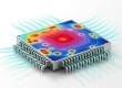

The rapid adoption of AI is reshaping how data centers are designed, built, and operated. As compute densities rise and power is concentrated into fewer, hotter chips, traditional air-cooled architectures are reaching their practical limits. In response, liquid cooling—particularly direct-to-chip approaches— has become central to liquid cooling system design in modern data centers.
At the heart of every liquid-cooled system is thermal fluidics: the relationship between flow, pressure, and heat transfer. These fundamentals determine not only how effectively heat is removed from processors, but also how efficiently a system operates, how reliably it scales, and how well individual components work together as part of a broader cooling ecosystem.
This blog takes a foundational look at thermal fluidics and the key infrastructure components that support liquid cooling in AI data centers. From flow regimes and pressure drop to cold plates, CDUs, manifolds, and quick disconnects, we’ll explore how these elements interact—and why understanding them as a system is essential for designing robust, high-density cooling architectures.
Thermal Fluidics Fundamentals: Flow and Pressure in Liquid Cooling
Flow Rate: Flow rate (volumetric flow) refers to the volume of liquid that moves through a system per unit of time. Higher flow improves heat transfer by increasing the amount of coolant passing over hot surfaces. However, excessive flow can lead to increased pressure requirements and energy consumption.
Pressure Drop: Pressure drop refers to the loss of pressure that a liquid experiences as it flows through the cooling system. Every component—such as cold plates, manifolds and quick disconnects—introduces resistance. Managing pressure drop is essential because it directly impacts pump power draw: the more resistance in the system, the harder the pump must work, consuming more energy. Keeping pressure drop in check ensures the pump can maintain adequate flow without excessive strain.
These two factors are closely linked: as pressure drop increases, more pumping power is required to maintain the target flow rate. Understanding this relationship is critical for designing systems that balance thermal performance with energy efficiency.

Flow Regimes in Liquid Cooling: Laminar and Transitional Flow
Laminar Flow: Laminar flow occurs when liquid moves in smooth, parallel layers without chaotic motion and mixing. This approach is common in microchannel cold plate designs, which have reached a high level of maturity in the data center cooling market. Laminar flow typically operates at lower flow rates (around 1.5–2 LPM in cold plates used for high-power applications), reducing pump energy requirements and improving overall system efficiency. However, the trade-off is thermal performance at the chip level. Laminar flow can struggle to address localized heat flux, which is increasingly common in modern GPU architectures and AI workloads. As a result, some cooling providers are exploring hybrid architectures that combine laminar and turbulent characteristics.
Transitional Flow: Transitional flow describes a localized, short‑lived state between laminar and fully turbulent behavior. This allows cooling architectures to leverage the benefits of turbulent flow—which is traditionally described as chaotic fluid motion with fluctuating velocity and pressure—without requiring a fully turbulent system. Turbulence‑like behavior can boost heat transfer by thinning the thermal boundary layer that naturally forms on hot surfaces, making it easier to dissipate heat.

In jet impingement cold plates, the fluid at the jet exit becomes energetic enough to disrupt this boundary layer at the moment of impingement, improving heat transfer. Immediately afterward, the flow relaminarizes, especially in captive jet designs, preserving stable hydraulics and avoiding the steep pumping penalties associated with fully turbulent operation.
This controlled, transitional behavior provides many of the thermal advantages commonly attributed to turbulent flow while keeping the overall cooling loop predominantly laminar. The result is strong thermal performance for high‑density, AI workloads while maintaining manageable pumping power, pressure drop, and overall system overhead.
The bottom line: Both laminar and transitional regimes have their place in liquid cooling. The right choice depends on workload characteristics, thermal requirements, and how well the cooling architecture integrates with existing infrastructure. Jet impingement designs that leverage transitional behavior at the point of heat pickup offer a compelling middle ground—boosting thermal performance where needed while maintaining efficient, largely laminar operation throughout the rest of the system.
Heat Load as the Driver: How Processors Define Flow Requirements
When designing a cold plate solution, the goal is simple: dissipate the TDP as efficiently as possible. Lower TDP ratings (around 100–400 W) can often be managed with air-cooled heat sinks. But as power density climbs—especially in AI and HPC environments—liquid cooling becomes necessary. Without a properly designed liquid cooling system, your servers with the latest AI processors won’t even power on.
Cold plate technology is typically designed with a specific processor or processor family in mind, ensuring compatibility with its thermal profile and performance requirements. This alignment is critical because flow requirements ultimately stem from the chip’s heat output.
Core Components of Data Center Liquid Cooling Infrastructure
Cold Plates and Coolant Distribution Units – Primary Heat Removal & Control
Coolant Distribution Units (CDUs): Think of the CDU as the central control system of a liquid cooling setup. It regulates temperature, monitors flow, and ensures the right amount of coolant reaches each part of the system. This makes CDUs essential for maintaining stable thermal conditions in high-density, scalable computing environments.
In operation, CDUs circulate coolant through cold plates or other heat exchangers mounted on processors or GPUs. After absorbing heat from the processor, the coolant returns to the CDU, where it either transfers that heat to the facility water loop or dissipates it via an air-cooled radiator. This closed-loop process enables higher compute densities while reducing reliance on traditional air cooling.
Liquid Cold Plates: Cold plates are the direct interface between the coolant and the heat-generating components. Their design must align with the system’s flow characteristics to ensure uniform processor temperatures. Greater temperature fluctuations put additional strain on hardware, reducing performance and shortening lifespan. Flow maldistribution can lead to hotspots, reduced performance, and even hardware failure. Precision engineering of cold plates is critical for achieving optimal thermal performance at the chip level.
Manifolds and Quick Disconnects – Distribution, Balance & Serviceability
In-Rack Manifolds: Manifolds distribute coolant uniformly to all server cold plates. Continuous fluid circulation is essential, but excessive pressure drop within the manifold forces pumps to work harder than necessary. Every bit of lost pressure is power that could be used for actual cooling. Proper manifold design ensures balanced flow and minimizes unnecessary strain on the system.
Quick Disconnects (QDs): Quick disconnect couplings allow rapid, spill-free connection and disconnection of coolant lines to servers—critical for maintenance, upgrades, and hot-swapping without shutting down IT equipment or the cooling system. High-quality QDs enable fast, tool-free service while minimizing leakage and pressure drop, preserving system integrity and performance.
Choosing the right manifolds and QDs can mean the difference between a high-performing system and one plagued by inefficiencies. Poorly designed components can lead to uneven flow distribution, forcing customers to spend more on pumping power or additional technology to compensate. Proper design ensures every server gets the right amount of coolant—without unnecessary cost or complexity.
Selecting a Liquid Cooling Partner with System-Level Expertise
When you introduce the complexity and high demand of AI into your environment, you need a partner who can support you end-to-end—from co-development and design to commissioning, services, and ongoing support.
Liquid cooling also blurs traditional boundaries between IT and facilities. Components like pumps, manifolds, and coolant loops don’t fit neatly into legacy cooling models. As noted in Uptime Institute’s June 2025 report Hold the Line: Liquid Cooling’s Division of Labor, “the conventional line of demarcation that divides the responsibilities of facilities and IT teams does not easily map to DLC equipment.” Without the right expertise, this ambiguity can stall deployments, introduce unnecessary risk, and undermine long-term operational sustainability. The right partner doesn’t just deliver hardware; they provide guidance, integration, and support to ensure your liquid cooling strategy scales with your business. In a market moving at AI speed, collaboration isn’t optional, it’s critical.
Designing Liquid Cooling Systems from First Principles
From cold plates and CDUs to manifolds and quick disconnects, every element in a liquid cooling loop influences overall performance, efficiency, and reliability. Poorly balanced flow or unmanaged pressure drop can undermine even the most advanced cooling technology, while well-designed infrastructure enables consistent thermal performance and long-term scalability.
Designing liquid cooling systems for AI compute requires more than selecting hardware; it demands a systems-level approach and partners who understand the full cooling ecosystem. By grounding design decisions in thermal fluidics fundamentals and infrastructure awareness, data center operators can build liquid-cooled environments that are resilient, efficient, and ready to support the next generation of high-density compute.