
Current State of Electronics Innovation
Across military, government, and industrial sectors, electronic devices have been proliferating. Devices have continually become more capable while simultaneously shrinking in size, following the approximate cadence of Moore’s Law. This may seem like a given in today’s technological landscape, but it is quite a remarkable trend: continuing increases in throughput, with furthering reductions in size.
This trend has led to impressive capabilities. Artificial intelligence processors enable complex machine learning algorithms, where services like Google Photos evaluate over 1 billion photos each day. Military radar electronics have incorporated novel semiconductor materials like Gallium Nitride and Silicon Carbide to achieve increased measurement range and frequencies. Performance electric vehicles are available at the consumer level, sporting onboard power conversion equipment processing 100s of kilowatts to allow for 0-60mph accelerations in less than 2.5 seconds. The list goes on.

Figure 1: Cross-industry trend of power density continually increasing on semiconductor devices [1,2,3].
Emerging Thermal Management Challenges
An underdiscussed byproduct of this exponential growth is the thermal management of waste heat. With more computations, higher frequency bands, and higher voltage power conversion occurring on miniaturizing chips, large amounts of waste heat become trapped on small device areas. As a result, electronic devices and their accompanying systems are increasingly exposed to the ills of high temperature operation: compromised device efficiency, reduced device lifetime, high cooling system energy usage, bulky cooling hardware, and unsatisfying performance limitations.
Traditionally, electronics have been cooled using air. The most basic systems simply allow the device to cool passively with the surrounding air, sometimes using copper vias in the printed circuit boards to spread the heat over a larger area. More advanced air thermal management systems utilize finned metal heat sinks and forced chilled air systems to actively dissipate heat. But air quickly reaches its limits, becoming prohibitively power-, size-, and noise-intensive to effectively manage device temperatures.
As a result, higher performing devices have transitioned to liquid cooling systems. Liquid coolants can be as high as 30x more thermally conductive than air, allowing electronics to be more efficiently cooled. The adoption of liquid cooling systems has been a device designer’s sandbox, enabling new designs with over an order of magnitude increase in power density and capability. But amazingly, with the seemingly boundless innovation in semiconductor electronics, even traditional liquid cooling systems are reaching their limits.
Traditional Liquid Cooling: Conductive Metal Plates and Thermal Interface Materials
The current landscape of liquid cooling technology is dominated by conductive metal plates, or “cold plates”. Devices are attached on the surface of the cold plate, which contains internal channels for coolant to flow. Heat travels from the device into the cold plate, spreads throughout the plate due to the metal’s high thermal conductivity, and is removed via convection into the cool fluid flowing in the plate.
While this works very effectively for many electronic devices, high thermal density devices strain this cooling methodology. The reason is a subtlety in the implementation of these cold plates: when attaching a device to a cold plate, microscale roughness on the joining surfaces results in air gaps. These serve as an insulating blanket, resulting in poor heat transmission from the device to the metal plate.
To remedy this issue, a thermal interface material (TIM) is administered between the metal plate and the device. Often a paste or epoxy, this TIM fills the gaps with a more thermally conductive material, forming a lower resistance pathway for heat to flow.
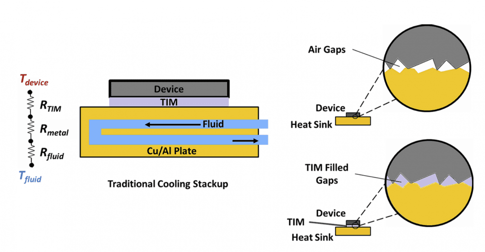
Figure 2: Traditional liquid cooling methodology using conductive metal plates with thermal interface materials (TIMs). TIMs are used to provide an improved thermal pathway between the device and the cooling plate, but start to suffer at high thermal densities.
Unfortunately, even though TIM-filled gaps are more conductive than air gaps, they can still be a significant resistance for heat flow. The resistance is typically manageable in modest heat-dissipating devices, but becomes worse as the thermal density increases.
As a quick example, typical TIMs have thermal resistances per unit area around 0.1 °C / (W/cm^2) [4]. For typical liquid cooled devices with thermal densities near 50 W/cm^2, there is a ≈5°C temperature drop across the TIM. This is not ideal but is manageable for systems with low ambient temperatures.
However, for emerging devices that eclipse 250 W/cm^2 thermal densities, the temperature drop becomes ≈25°C across the TIM. This is prohibitive for most systems, and only gets worse as the highest thermal density devices eclipse 1,000 W/cm^2. To effectively cool devices with these power densities, a different thermal interfacing technique must be employed.
A Different Thermal Interface Design: Coolant-on-Chip
If the TIM is offering a large resistance for heat to flow, how do we remove the TIM? Cold plates to date have internal cooling channels, with metal material forming a barrier between the coolant and the device. But if a cooling module is configured to have the coolant directly contact the chip, there is no barrier and therefore no TIM is needed.
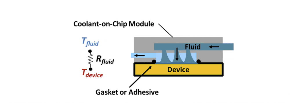
Figure 3: An alternative thermal interface methodology. Coolant is brought directly in contact with the chip surface, minimizing the thermal resistance from device to fluid.
In the coolant-on-chip methodology, the cooling module now seals directly to the device. This means there are no intermediate layers, and the resistance from hot surface to cool fluid is minimized. By employing a high effectiveness convection technique at the device surface, the necessity of heat spreading into a large metal plate is obviated and results in a very compact solution.
Further, because the cooling module structure no longer participates in the heat transfer pathway, it need not be made from a highly thermally conductive material. This provides system designers with significant material flexibility. It can also be an important tool in a designer’s toolbox to help address detailed issues such as: higher reliability via materials with well-matched coefficients of thermal expansion; longer lifetimes from modules with better corrosion prevention characteristics; and foundry-level fabrication potential of cooling modules using semiconductor materials.
Conclusion
With increasing power densities, adequate thermal management of devices is becoming challenging. The traditional method of liquid cooling via thermal interface materials and high conductivity heat spreaders is reaching its limits. By employing coolant-on-chip methodologies, significant reductions in thermal resistance from chip to coolant can help keep devices at safe temperatures.
References
[1] Rupp, Karl. 42 Years of Microprocessor Trend Data. 15 Feb. 2018, www.karlrupp.net/2018/02/42-years-of-microprocessor-trend-data/.
[2] J. Y. Tsao et al., “Ultrawide‐Bandgap Semiconductors: Research Opportunities and Challenges,” Advanced Electronic Materials, Vol. 4, No. 1, January 2018, Article No. 1600501.
[3] Dalal, Dhaval, and C. Quinn. “Empowering the electronics industry: A power technology roadmap.” Proc. IEEE Appl. Power Electron. Conf. and Exposition, Tampa, FL. 2017.
[4] Thermal Interface Materials for Electronics Cooling. Parker Chomerics, Mar. 2020.