

Although fluid fittings for liquid cooling systems are simple in concept, the actual execution of locating, ordering, and installing the correct fitting can turn into quite an exercise. For example, how many times have you had a string of three different fittings connected between two components because you did not have the perfect fitting on hand? How many hours have you spent searching McMaster trying to use the proper search filters to locate and order the right fitting? How many times have you thought you ordered the correct fitting, only for it to arrive and realize something was amiss? This post will discuss a simple convention for identifying fluid fittings between two interfaces, with the goal of simplifying liquid cooling system design.
In liquid cooling systems, there are a large variety of different components- pumps, heat exchangers, cooling plates, tubing, filters, valves, etc. When working with these components, there almost always comes a point where there is a connection incompatibility:
-
Tapered vs. parallel threads
-
Tube/pipe size differences
-
Differences in tube/pipe size standards (e.g. ID vs. OD)
-
Differences in system material (e.g. brass, steel, plastic, aluminum)
-
Material compatibility concerns (e.g. pressure tolerance, corrosion, material strength).
In light of these challenges, a simple convention could go a long way in simplifying the identification and acquisition of fittings. JetCool makes device-level cooling modules, so here the distinction is made between the “system” interface and the “module” interface, but this can be applied to any fitting connection. Figure 1 below introduces the convention:
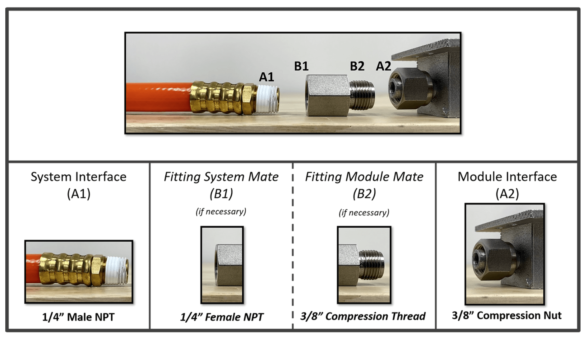
Figure 1: Graphical depiction of JetCool’s fitting convention. In this example, the system uses a 1/4” male NPT fitting, and it needs to adapt to a 3/8” compression nut on the Jetcool module.
This can really simplify things. In the fortunate cases where A1 and A2 are a matching pair, they can simply be attached with no headache. But in all other cases, there is a required fitting in between, as defined by B1 on the system side and B2 on the module side. To unlock this fitting convention, Figure 2 shows a matrix populated by web links for the required fitting in the intersecting square:
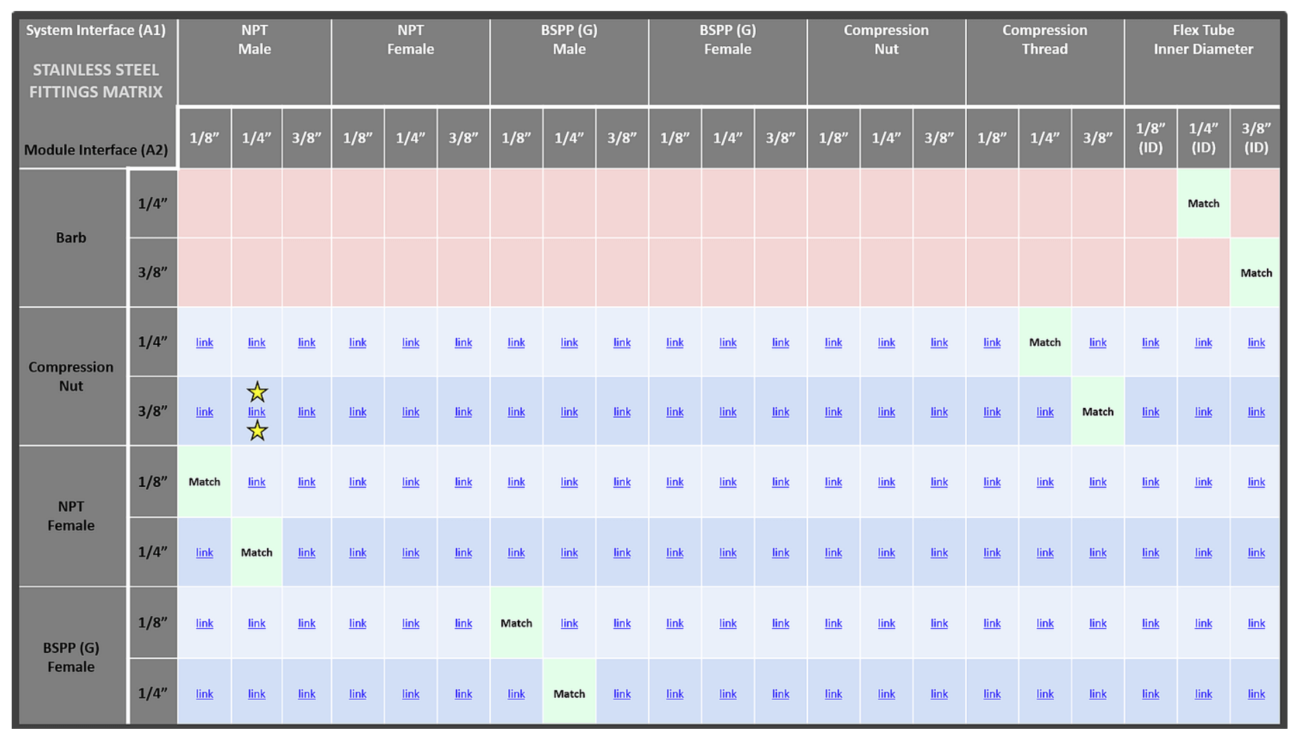
Figure 2: A matrix displaying a variety of possible system interfaces (A1) and the fittings required to adapt to typical JetCool module interfaces (A2) [1,2,3]. JetCool uses this tool to design and deliver plug-and-play modules into fluidic systems. The example in Figure 1 is indicated by the yellow stars. Note this is an abbreviated version of the matrix; JetCool can adapt to any system interface.
The guide shown is for stainless steel fittings as an example, but the same can be done for brass, plastic, and any other fitting material required. With system interface, A1 going horizontally across the top and module interface A2 going vertically down on the left side, the landscape for fitting interfaces becomes immediately apparent. There are some combinations in green that are a direct match (A1 mates with A2), while others in red are not easily solved by a single fitting. Also note that there are many more possibilities for the A2 interface, but these are the most used in JetCool module designs.
Conclusion
With a fittings convention and accompanying matrix defined, liquid cooling system design can be simplified. By keeping a library of the fittings in the matrix with information regarding their dimensions, pressure rating, cost, and any other important considerations, the determination and acquisition of fittings become a much more hassle-free and enjoyable experience.
References
[1] “How to Identify and Measure Fittings” McMaster-Carr, http://www.mcmaster.com/fittings.
[2] “Fittings” Swagelok, http://www.swagelok.com/en/product/fittings
[3] “Fittings & Quick Disconnects”, Koolance, koolance.com/products.