

As electronic devices miniaturize, what happens to our cooling solutions? It’d be favorable if the heat sink area shrank concurrently so that we could fit more devices in the same space as before, and therefore achieve higher functionality in a smaller size. But with smaller devices comes higher power densities, making cooling that much more difficult. This begs the question: just how does the effectiveness of the cooling method affect the size of the solution?
We know that heat transfer goes as:
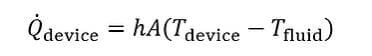
where Q_dot_device is the waste heat from the device (W), h is the heat transfer coefficient of the cooling method being applied (W/m^2°C), A is the area over which heat is being transferred (m^2), and T_device and T_fluid are the temperatures of the device and rejection fluid, respectively (°C). In this equation, the inherent cooling effectiveness is represented by h, as this corresponds to how well a given cooling method can remove heat for a given area and temperature difference.
Shown below is a table outlining the heat transfer coefficients, h, for various cooling techniques that use air or water:

Note the ranges account for a variety of factors such as flow rates, feature sizes, temperature gradients, etc. Considerations such as pressure drop, input power, and manufacturability tend to get more prohibitive at the upper ends of the ranges, so use caution when applying these heat transfer coefficients.
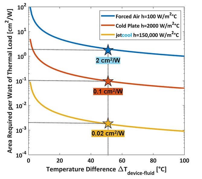
To illustrate how these heat transfer coefficients relate to size, we’ll plot the size required versus temperature difference for a few select cooling methods:

Let’s take a look at the general trends of this plot:
-
The higher the temperature difference we are working with, the less area is needed to cool down the device;
-
Cooling methods with higher heat transfer coefficients require less cooling area;
-
Higher power devices require more cooling area.
To further understand the graphic, let’s carry out an example to get a sense of the numbers we are working with. Let’s say we have a device with total power of 300W operating at 66% efficiency, corresponding to 200W of output power and 100W of waste heat. Let’s also say that our target device temperature is 50°C above the ambient cooling fluid. If we read the areas corresponding to where the stars are located on the graph below, we will get the approximate required areas per unit thermal load:
We can now multiply this number by the 100W of waste heat from our device to get the required cooling area:
-
Forced Air: (2 cm^2/W) x (100W) = 200cm^2
-
Cold Plate: (0.1 cm^2/W) x (100W) = 10cm^2
-
JetCool: (0.02 cm^2/W) x (100W) = 0.2cm^2
This means, to cool the 100W device using a fan, the cooling area needs to be 200cm^2. A typical 100W device might be around 5cm^2, meaning the heat sink area needs to be ~40X larger than the actual device footprint area! This is why air heat sinks have so many of those long, thin fins- they need to increase the surface area of the heat sink to achieve adequate cooling of the device.
Further, a cold plate requires 10cm^2 for cooling, implying we need about 2x the area of the 5cm^2 device – a big improvement over the fan, but still extending beyond the footprint of the device. This makes sense, as usually cold plates have a couple of heat loads on them separated by a few inches. That is, they are not densely packed.
In the case of JetCool cooling, the cooling area required of 0.2cm^2 is actually smaller than the device footprint, which would allow for a cooling solution to be directly mounted within the extents of the device. This would allow very densely packed arrays of devices with no loss in performance. Alternatively, we could increase the device power density while keeping the cooling solution within the device footprint.
Of course, these numbers will change for devices running at different temperature differences, device powers, and device efficiencies, but the trend is clear: cooling technologies with higher heat transfer coefficients can be much more compact!
very clear and good article easy to understand. Thank you